Table des matières
In the previous article, we looked at the history of IFC and the basics of how the schema and file formats work. That gave us the big picture and now it’s time to delve into an IFC file to see how the information is structured.
This article will focus on the overall organisation of IFC files and their core entities — the digital building blocks that represent walls, spaces, buildings, and more. In Part 3, we’ll dive deeper into properties and relationships.
The Structure of an IFC File
When working with IFC Schema in openBIM projects, understanding the IFC file structure is crucial for architects, engineers, and BIM coordinators.
An IFC file may look like a block of cryptic text when you open it in a text editor, but it follows a clear logic. It is divided into two main parts: 📂
- Header Section – metadata about the file itself.
- Data Section – the actual project data: entities, attributes, and their connections.
Header Section
The header defines the context of an IFC file. It tells the receiving software what it’s looking at. Typical content includes: 📝
- File description: purpose, originating system, schema version.
- File name: project name, author, organisation, timestamp.
- File schema: identifies which IFC release is used (e.g. IFC2x3, IFC4).
Without the header, software would not know which rules to apply to the following data. For example the header is crucial to interpret the IFC Schema version and ensure compatibility. Think of it as the cover page of a technical report — without it, the rest is much harder to interpret.
ISO-10303-21;HEADER;FILE_DESCRIPTION(('no view'),'2;1'); FILE_NAME('C://der/pfad/zur/datei.ifc',('Linda'),('Software Name', 'Konrad-Zu 1,Germany'), 'EDMsix Version 2.0100.09 Sep 7 2016','Allplan 2019.1 24.06.2019 16:10:06',''); FILE_SCHEMA(('IFC4'));ENDSEC;
Data Section
The IFC data section contains the actual project information. Each object in the project is represented as an instance of an entity from the schema. 📊
Every instance is given:
- a line number (for referencing within the file),
- a GUID (Globally Unique Identifier),
- and a set of attributes (geometry, placement, material, etc.).
Here’s a simplified example of a wall in STEP syntax:
#42 = IFCPROJECT('2C45vBrGbB_w_CB97snkya', ...);#101 = IFCBUILDING('0oHfLk3df5wPq6', ...);#201 = IFCBUILDINGSTOREY('3K9xGv4C5T$zQq', ...);#301 = IFCWALLSTANDARDCASE('1Lm8y2FfH9R7Ts', 'Wall-001', ...);
The above snippet illustrates how IFC entities are referenced and nested, which is a defining feature of the IFC Schema. For example, the wall (#301) belongs to a storey (#201), which belongs to a building (#101), which in turn belongs to the project (#42).
The IFC Schema Layers
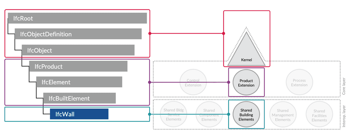
To make sense of this, it helps to know how IFC is layered internally. Entities aren’t all on the same level — they are organised in a hierarchy of layers that build on each other:
- Kernel (lowest layer): The foundation. Defines the most generic entities and concepts used everywhere. Examples: IfcRoot, IfcObjectDefinition, IfcRelationship.
- Core Layer: Adds basic definitions for objects and processes. Here we find IfcObject, IfcTypeObject, IfcProduct, and IfcProcess. These entities distinguish physical objects from activities, controls, or groups.
- Interoperability Layer (Shared layer): Defines elements that are common to multiple domains. For example, IfcWall, IfcSlab, IfcBeam, IfcDoor, and IfcWindow. These are widely used across architecture, structural analysis, and MEP.
- Domain Layers (on top of Interop): Specialised sets of entities for specific disciplines (architecture, structural analysis, HVAC, electrical, etc.).

These layers (Kernel, Core, Interoperability, Domain) form the backbone of the Industry Foundation Classes (IFC) Schema, ensuring both flexibility and interoperability across BIM tools. This layering is what makes IFC both flexible, extendable (new domains can add new entities) and consistent (everything shares a common kernel).
Inheritance in IFC
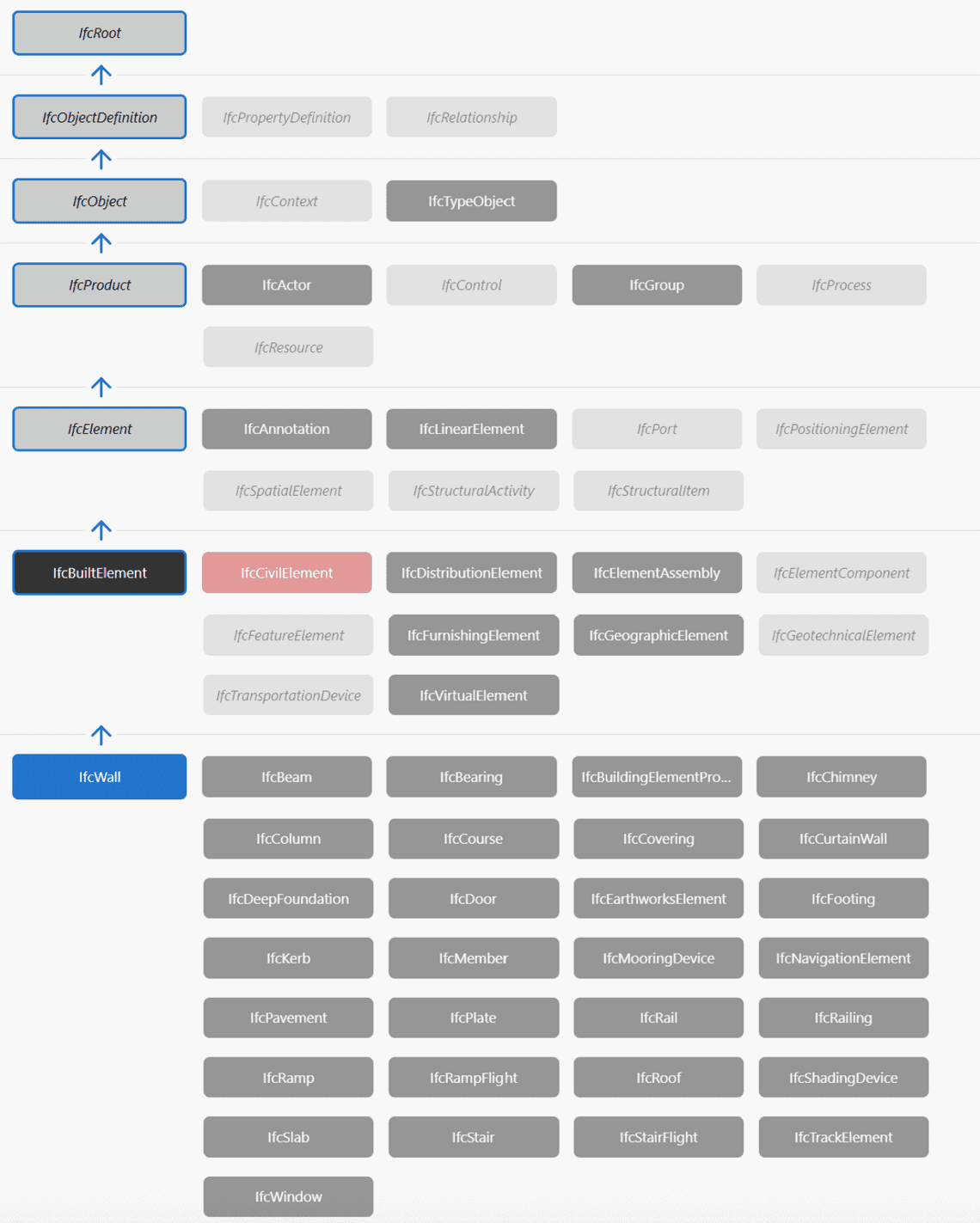
In addition to layering, the IFC Schema makes heavy use of inheritance — a concept borrowed from object-oriented programming. IFC Entities don’t exist in isolation; they inherit attributes and behaviour from higher-level entities.
Take the example of IfcWall:
- At the top, IfcRoot gives every object a GlobalId, owner history, and basic identification.
- From IfcObjectDefinition, it inherits the ability to be part of relationships.
- From IfcObject, it gains a name, description, and type linkage.
- From IfcProduct, it inherits geometric representation and placement.
- From IfcElement, it inherits construction-related attributes (tag, connections).
- Finally, as IfcWall (in the shared/interoperability layer), it adds wall-specific meaning and geometry rules.

This hierarchical inheritance has two big advantages:
- Consistency: All entities share common attributes like GlobalId, ownership, and placement.
- Reusability: New entities can be defined by extending existing ones instead of reinventing the wheel.
The downside? It can make IFC files look abstract and verbose, since attributes aren’t always defined where you expect them — they might come from three levels up the inheritance chain.
Entities in IFC
Entities are the backbone of IFC. Each entity describes a certain kind of object or concept and defines which attributes it can have (e.g. IfcWall, IfcDoor). 🧱
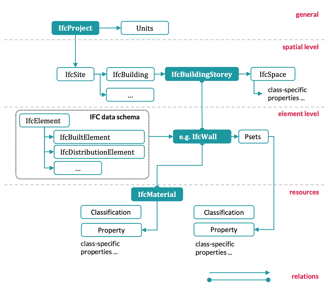
We can group entities into three main categories: physical elements, spatial structure, and resources.
Physical Elements
Physical elements are the most important parts of the IFC Schema, since they map directly to building elements in BIM models. Examples include:
- IfcWall / IfcWallStandardCase: standard vertical walls.
- IfcDoor / IfcWindow: openings and closures.
- IfcBeam / IfcColumn / IfcSlab: structural elements.
- IfcStair / IfcRoof / IfcCovering: additional architectural elements.
Geometry Representations
One of the tricky parts of IFC is that geometry can be defined in different ways:
- Extruded solids: most common, e.g. a wall defined by a 2D profile extruded vertically.
- Swept solids: objects defined by moving a profile along a path (e.g. handrails).
- Boundary representations (BRep): exact 3D surfaces, usually from CAD or freeform geometry.
- Mapped geometry: reuse of geometry definitions, e.g. repeating identical windows.
Here is a simple wall with extruded geometry:
#100 = IFCCARTESIANPOINT((0.0,0.0));#101 = IFCAXIS2PLACEMENT2D(#100, $);#102 = IFCRECTANGLEPROFILEDEF(.AREA., 'Wall Profile', #101, 200.0, 3000.0);#103 = IFCDIRECTION((0.0,0.0,1.0));#104 = IFCAXIS2PLACEMENT3D(#100, #103, $);#105 = IFCEXTRUDEDAREASOLID(#102, #104, #103, 3000.0);#106 = IFCSHAPEREPRESENTATION(#context, 'Body', 'SweptSolid', (#105));#107 = IFCPRODUCTDEFINITIONSHAPE($,$,(#106));#108 = IFCWALLSTANDARDCASE('1Lm8y2FfH9R7Ts', 'Wall-001', $, $, #localplacement, #107, $);
In the above example a wall is geometrically represented using an extruded rectangular profile (200 mm × 3000 mm × 3000 mm):
- #100–#101 define a 2D coordinate system.
- #102 defines a rectangular wall profile: 200 mm thick, 3000 mm long.
- #103–#104 define the extrusion direction (Z-axis).
- #105 creates the extruded solid, 3000 mm high.
- #106–#107 package the solid into a shape representation.
- #108 defines the wall entity, referencing the geometry.
Placement in 3D-Space
Geometry tells us what an element looks like, but not where it belongs in the building. For that, IFC uses a placement hierarchy.
Every element has a local placement defined by:
- IfcLocalPlacement → defines position and orientation relative to another object.
- This references an IfcAxis2Placement (2D or 3D) with an origin point and direction vectors.
Placements are usually chained:
- A wall is placed relative to its storey.
- The storey is placed relative to the building.
- The building is placed relative to the site.
- The site is placed in world coordinates (e.g. real-world georeferencing with IfcMapConversion).
This hierarchy mirrors real construction: a wall isn’t just floating in 3D space; it has a defined location inside a storey, inside a building, on a site.
Here is an example of a wall placed in a storey:
#200 = IFCCARTESIANPOINT((0.0,0.0,0.0));#201 = IFCAXIS2PLACEMENT3D(#200, $, $);#202 = IFCLOCALPLACEMENT($, #201); -- Placement of Ground Floor storey#210 = IFCCARTESIANPOINT((5000.0,2000.0,0.0));#211 = IFCAXIS2PLACEMENT3D(#210, $, $);#212 = IFCLOCALPLACEMENT(#202, #211); -- Placement of Wall relative to Storey#220 = IFCBUILDINGSTOREY('3K9xGv4C5T$zQq', 'Ground Floor', $, $, #202, $, $);#230 = IFCWALLSTANDARDCASE('1Lm8y2FfH9R7Ts', 'Wall-001', $, $, #212, #geometry, $);
- #202 defines the placement of the “Ground Floor” storey.
- #212 defines the wall’s placement relative to the storey.
- #230 is the wall itself, linked to its placement and geometry.
This placement system is one reason the IFC file structure is reliable for digital construction workflows — from design to on-site execution.
Spatial Structure
Spatial entities provide the hierarchical backbone of every IFC file, being a key part of the IFC Schema. They are mandatory for organising all physical elements.
The hierarchy typically looks like this:
- IfcProject → the overall project context.
- IfcSite → geographic location and terrain.
- IfcBuilding → the building(s) at the site.
- IfcBuildingStorey → individual floors or levels.
- IfcSpace → functional areas (rooms, zones).
Each element in the model must be contained in this hierarchy through relationships. For example, walls and slabs are “contained” in a storey, which belongs to a building.
Resources
Resources in IFC are entities that define supporting information used by multiple elements.
Some key examples:
- IfcMaterial – defines materials (e.g. concrete, steel, timber).
- IfcProfileDef – defines cross-sections (rectangular, circular, I-profile) for beams and columns.
- IfcTypeObject – reusable types of objects (e.g. “Door Type D01”), which can then be instantiated multiple times.
- IfcActor / IfcOrganization – resources that describe the stakeholders of a project (companies, people).
By separating resources from physical elements, gives the ability to the IFC files to support consistency and reusability across the IFC Schema. If the material definition changes (e.g. switch from C30/37 to C35/45 concrete), all elements using that material can be updated accordingly.
Example Walkthrough: A Wall in Context
To better understand the IFC file structure, let’s walk through a simple but complete example: a wall positioned in context within a building storey. 🧱📐
#10 = IFCPROJECT('2C45vBrGbB_w_CB97snkya', $, 'Demo Project', $, $, $, $, (#50));#20 = IFCSITE('0oHfLk3df5wPq6', 'Main Site', $, $, #100, $, $, $, .ELEMENT., $);#30 = IFCBUILDING('1abCDeFgHiJkLmNo', 'Building A', $, $, #110, $, $, $, .ELEMENT., $);#40 = IFCBUILDINGSTOREY('3K9xGv4C5T$zQq', 'Ground Floor', $, $, #120, $, $, $, .ELEMENT., $);#100 = IFCLOCALPLACEMENT($, #200); -- Placement of site#110 = IFCLOCALPLACEMENT(#100, #210); -- Placement of building relative to site#120 = IFCLOCALPLACEMENT(#110, #220); -- Placement of storey relative to building#130 = IFCLOCALPLACEMENT(#120, #230); -- Placement of wall relative to storey#200 = IFCAXIS2PLACEMENT3D(#500, $, $);#210 = IFCAXIS2PLACEMENT3D(#501, $, $);#220 = IFCAXIS2PLACEMENT3D(#502, $, $);#230 = IFCAXIS2PLACEMENT3D(#503, $, $);#500 = IFCCARTESIANPOINT((0.0,0.0,0.0));#501 = IFCCARTESIANPOINT((0.0,0.0,0.0));#502 = IFCCARTESIANPOINT((0.0,0.0,0.0));#503 = IFCCARTESIANPOINT((5000.0,2000.0,0.0)); -- Wall offset 5 m X, 2 m Y#600 = IFCCARTESIANPOINT((0.0,0.0));#601 = IFCAXIS2PLACEMENT2D(#600, $);#602 = IFCRECTANGLEPROFILEDEF(.AREA., 'Wall Profile', #601, 200.0, 3000.0);#603 = IFCDIRECTION((0.0,0.0,1.0));#604 = IFCAXIS2PLACEMENT3D(#500, #603, $);#605 = IFCEXTRUDEDAREASOLID(#602, #604, #603, 3000.0);#700 = IFCSHAPEREPRESENTATION(#50, 'Body', 'SweptSolid', (#605));#710 = IFCPRODUCTDEFINITIONSHAPE($,$,(#700));#800 = IFCWALLSTANDARDCASE('1Lm8y2FfH9R7Ts', 'Wall-001', $, $, #130, #710, $);#900 = IFCRELAGGREGATES('rel-1', $, $, #10, (#20)); -- Project contains site#901 = IFCRELAGGREGATES('rel-2', $, $, #20, (#30)); -- Site contains building#902 = IFCRELAGGREGATES('rel-3', $, $, #30, (#40)); -- Building contains storey#903 = IFCRELCONTAINEDINSPATIALSTRUCTURE('rel-4', $, $, (#800), #40); -- Storey contains wall
- IfcProject defines the overall project.
- IfcSite defines the geographic location.
- IfcBuilding is linked to the site.
- IfcBuildingStorey defines “Ground Floor”.
- IfcWallStandardCase represents the wall.
- The wall is linked to the storey using IfcRelContainedInSpatialStructure.
- The wall has a material definition via IfcRelAssociatesMaterial.
- The wall has geometry defined by an extrusion.

This chain of entities and references is what gives the wall meaning. It’s not just a 3D block — it is a specific wall, in a specific storey, with a defined material, that software can interpret consistently.
Why Entities Matter
Entities may look abstract, but they are what make IFC different from a 3D model in a CAD tool. IFC is not just shapes — it’s structured information with identity, hierarchy, and meaning: ⚙️
- Identity: every element has a GUID.
- Hierarchy: every element belongs somewhere in the spatial structure.
- Consistency: resources like materials and types can be reused.
- Flexibility: geometry can be represented in multiple ways but tied to the same entity definition.
This is why IFC is so verbose and sometimes difficult to read — but also why it is powerful.
Conclusion (Part 2)
The IFC Schema is more than just a file format — it is the structured foundation for openBIM interoperability.
In this article, we opened up the IFC file and looked at its overall structure (header and data) and the entities it contains: physical elements, spatial hierarchy, and resources. ✅📌
In the next article (Part 3), we’ll continue with the properties and relationships that enrich entities and tie them together. This is where IFC really shows its strength: turning disconnected objects into an integrated digital model.
If you have any questions do not hesitate to leave a comment below!
