Table des matières
In Part 2 of this series, we explored the structure of IFC files and their core components: physical elements, the spatial hierarchy, and resources. That gave us a solid understanding of the building blocks inside the IFC Schema.
Now it’s time to look at how these components are given more detail (properties) and how they are connected (relationships). This is where the Industry Foundation Classes (IFC Schema) move beyond simple geometry into a true data model for openBIM.
Properties in the IFC Schema
Entities alone don’t tell us much. An IfcWall says “this is a wall,” but we also want to know: is it load-bearing, what’s the fire rating, what material is it made of? That’s where properties in IFC files come in play.
Property Sets (Psets)
- IFC uses Property Sets (Psets) to group related attributes.
- Standardised Psets exist for common elements, e.g.:
- Pset_WallCommon: fire rating, acoustic rating, load-bearing.
- Pset_DoorCommon: operation type, fire resistance, thermal transmittance.
- Properties can be simple (numbers, text) or complex (lists, references).
Here is a small example where the Pset_WindowCommon is assigned to an IfcWindow:
// Window instance (geometry/placement omitted for brevity)#2000 = IFCWINDOW('2mQf1xG3bPp8wQK1f2', 'Window-001', $, $, $, #LP, #SHAPE, $);// Property set with typical window attributes#2010 = IFCPROPERTYSET('pset-win-1', $, 'Pset_WindowCommon', $, (#2011, #2012, #2013, #2014));// Single-value properties#2011 = IFCPROPERTYSINGLEVALUE('IsExternal', $, IFCBOOLEAN(.T.), $);#2012 = IFCPROPERTYSINGLEVALUE('FireRating', $, IFCLABEL('EI30'), $);#2013 = IFCPROPERTYSINGLEVALUE('ThermalTransmittance', $, IFCTHERMALTRANSMITTANCEMEASURE(1.10), $); // W/(m2·K)#2014 = IFCPROPERTYSINGLEVALUE('AcousticRating', $, IFCLABEL('Rw 38 dB'), $);// Link the window to its property set#2020 = IFCRELDEFINESBYPROPERTIES('rel-prop-win-1', $, $, (#2000), #2010);
Window (#2000) is assigned Pset_WindowCommon with four attributes: external, fire rating, thermal transmittance, and acoustic rating. The above example shows how properties in IFC enrich otherwise geometric objects with functional and performance data.
Materials as Properties
While not stored in Psets, materials in IFC files play a similar role: they enrich elements with essential physical characteristics.
- IfcMaterial defines a single material (e.g. concrete, steel, brick).
- IfcMaterialLayerSet describes layered constructions (e.g. plaster + insulation + concrete).
- IfcMaterialConstituentSet handles materials that apply to parts of a component (e.g. frame vs. infill of a window).
Materials are linked to elements via IfcRelAssociatesMaterial, which works just like property assignment:
#1200 = IFCMATERIAL('Concrete');#1201 = IFCRELASSOCIATESMATERIAL('rel-mat', $, $, (#800), #1200);
Wall (#800) is associated with the material “Concrete”. Explicit material assignment ensures that when a model is exchanged, materials aren’t lost in translation, which is critical for structural analysis, cost estimation, and sustainability assessments.
Custom Properties in IFC
Not every project fits into the standard Psets. That’s why IFC also allows custom property sets, created by users or organisations.
- These follow the same structure but aren’t standardised.
- Useful for project-specific data (e.g. client requirements, sustainability metrics).
- Risk: without agreement, custom properties can reduce interoperability.
Example: Custom Sustainability Property
#3000 = IFCPROPERTYSET('pset-sust-1', $, 'Pset_Sustainability', $, (#3001));#3001 = IFCPROPERTYSINGLEVALUE('EmbodiedCarbon', $, IFCMASSMEASURE(250.0), 'kgCO2e/m2');#3010 = IFCRELDEFINESBYPROPERTIES('rel-prop-sust', $, $, (#800), #3000);
In the above example wall (#800) is assigned a custom sustainability property “EmbodiedCarbon = 250 kgCO₂e/m²”. You can how easily IFC can carry non-standard project data, such as embodied carbon, which is becoming increasingly relevant for sustainable construction workflows. But the ease of adding new properties is a double-edged sword: it is risky for interoperability — unless all parties agree, the data may not be recognised by downstream software.
👉 That’s why new standards like IDS (Information Delivery Specification) aim to formalise such custom requirements.
Relationships in the IFC Schema
If properties add detail, relationships in IFC files add structure. They describe how components connect: what belongs where, what fills what, what uses which material. 🔗
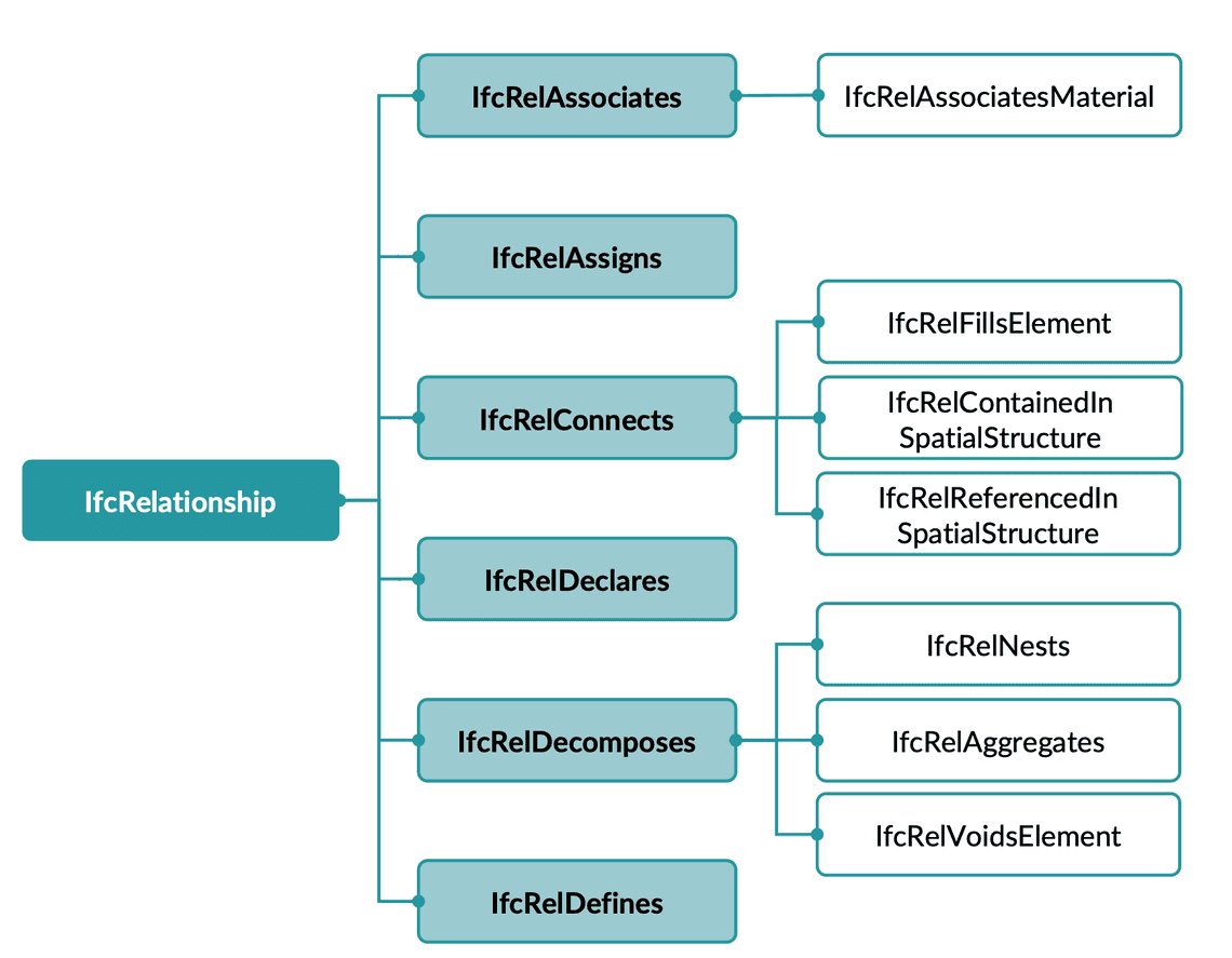
Relationships are first-class citizens in the IFC Schema. They are entities themselves (e.g. IfcRelContainedInSpatialStructure).

Containment and Aggregation
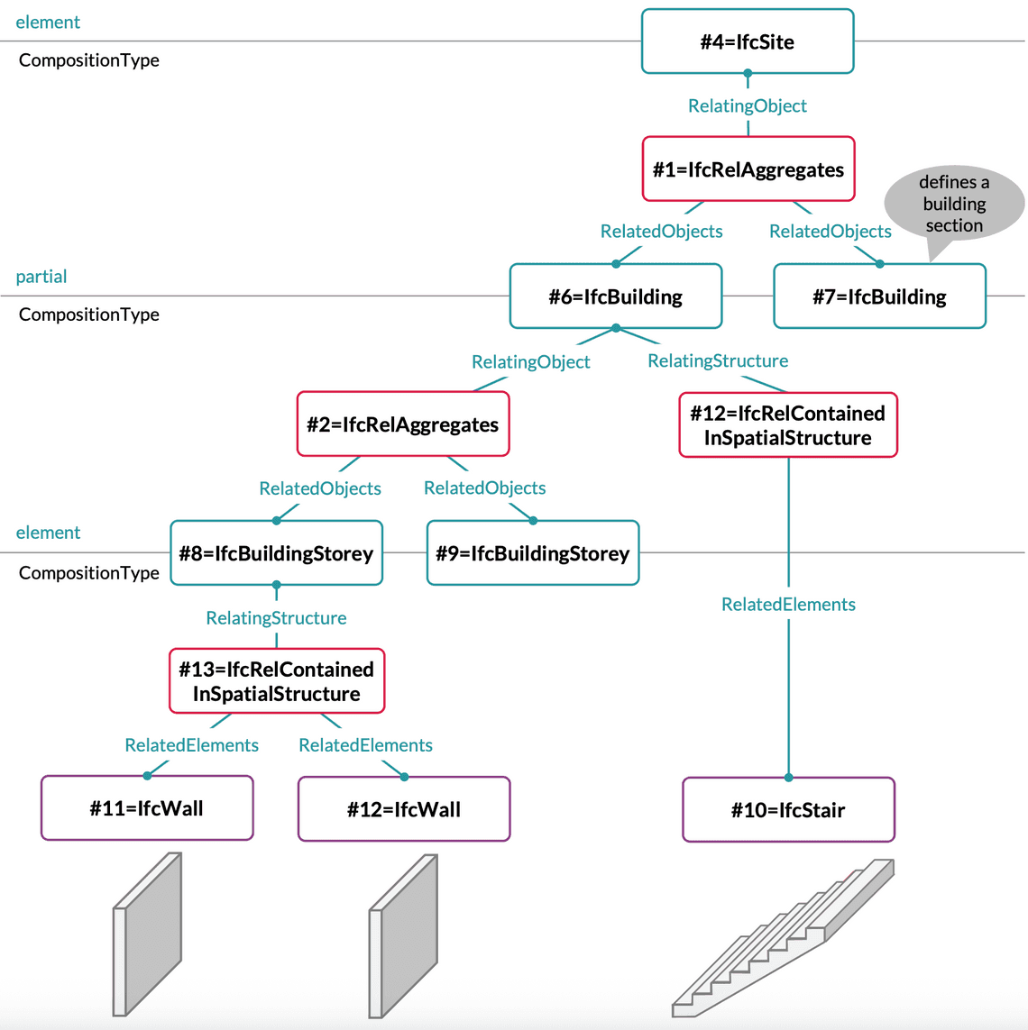
- IfcRelContainedInSpatialStructure → links elements to spatial levels (walls in storeys, storeys in buildings).
- IfcRelAggregates → groups components into larger wholes (a building made of storeys, a stair made of flights).

Connectivity
- IfcRelConnectsElements → defines physical connections (beam to column, wall to slab).
- IfcRelVoidsElement / IfcRelFillsElement → represent openings and their fillings (wall → opening → window).
#1100 = IFCOPENINGELEMENT('open-1', 'Wall Opening', $, $, #130, #geomOpening, $);#1101 = IFCRELVOIDSELEMENT('rel-void', $, $, #800, #1100); -- Wall has opening#1102 = IFCWINDOW('win-1', 'Window-001', $, $, #140, #geomWindow, $);#1103 = IFCRELFILLSELEMENT('rel-fill', $, $, #1100, #1102); -- Opening filled by window
In the above example wall (#800) contains an opening (#1100), which is then filled by a window (#1102).
Assignments
- IfcRelAssociatesMaterial → links elements to materials.
- IfcRelDefinesByType → assigns an element to a type object (e.g. all doors of Type D01).
- IfcRelDefinesByProperties → assigns a property set.
Example: Type Assignment with Properties and Material
// Wall type with property set#4000 = IFCWALLTYPE('WallType-1', 'Generic 200mm Concrete Wall', $, $, $, $, $, .STANDARD.);#4001 = IFCPROPERTYSET('pset-type-1', $, 'Pset_WallCommon', $, (#4002, #4003));#4002 = IFCPROPERTYSINGLEVALUE('FireRating', $, IFCLABEL('EI120'), $);#4003 = IFCPROPERTYSINGLEVALUE('IsExternal', $, IFCBOOLEAN(.T.), $);// Relating the property set to the wall type#4005 = IFCRELDEFINESBYPROPERTIES('rel-prop-type', $, $, (#4000), #4001);// Material definition for the wall type#4010 = IFCMATERIAL('Concrete');#4011 = IFCMATERIALLAYER(#4010, 0.20, $); -- 200 mm thickness#4012 = IFCMATERIALLAYERSET((#4011), 'Concrete Layer');#4013 = IFCRELASSOCIATESMATERIAL('rel-mat-type', $, $, (#4000), #4012);// Two wall instances in the model#4020=IFCWALL('0Bc7i64YzANAdct5Rq_I3f',#20,$,$,$,#15622,#15636,'2414787',.NOTDEFINED.);#4021=IFCWALL('0Bc7i64YzANAdct5Rq_I3k',#20, $,$,$,#15676,#15717,'2414788',.NOTDEFINED.);// Relating both walls to their common wall type#4025 = IFCRELDEFINESBYTYPE('rel-type', $, $, (#4020, #4021), #4000);
In the above example two wall instances (#4020, #4021) are linked to a common wall type (#4000). The type carries both a property set (fire rating and externality) and a material layer set (200 mm concrete), ensuring consistency across all instances.
Spatial Placement and Relationships Together
Geometry alone is not enough — spatial placement and relationships are combined to anchor every component in context. 📐🔗
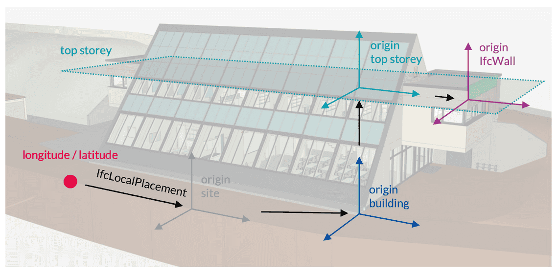
Every element has a local placement (via IfcLocalPlacement) that defines its position and orientation. These placements form a chain:
- A wall is placed relative to a storey.
- The storey is placed relative to the building.
- The building is placed relative to the site.
- The site can be placed in global coordinates using IfcMapConversion, aligning the model with GIS or survey data.
👉 This combination of relative and absolute placement ensures that a wall has both:
- a logical location in the building hierarchy (Ground Floor, east wing), and
- a real-world position (X/Y/Z coordinates, sometimes with latitude/longitude or projected CRS).
Why It Matters:
- Clash detection 🛑 — placements ensure that elements from different disciplines line up in the same coordinate space.
- Quantity takeoff 📏 — spatial relationships allow automated floor-area and volume calculations by storey or zone.
- Site layout 📍 — absolute placement (with IfcMapConversion) makes it possible to export models to GIS or surveying systems.
- Federation 🏗️ — multiple IFC files (architectural, structural, MEP) can be aligned correctly in a shared coordinate system.
Example: Placement Chain
#200 = IFCCARTESIANPOINT((0.0,0.0,0.0));#201 = IFCAXIS2PLACEMENT3D(#200, $, $);#202 = IFCLOCALPLACEMENT($, #201); -- Site placement at origin#203= IFCSITE('20FpTZCqJy2vhVJYtjuIce',#12,'Gel',$,$,#202,$,$,$,(51,28,57,28),(0,0,27,11),90,$,$);#210 = IFCCARTESIANPOINT((100.0,200.0,0.0));#211 = IFCAXIS2PLACEMENT3D(#210, $, $);#212 = IFCLOCALPLACEMENT(#202, #211); -- Building placed 100m east, 200m north of site origin#213= IFCBUILDING('00tMo7QcxqWdIGvc4sMN2A',#12,‘Geb\E4\ude',$,$,#212,$,$,$,$,$,$);#220 = IFCCARTESIANPOINT((0.0,0.0,0.0));#221 = IFCAXIS2PLACEMENT3D(#220, $, $);#222 = IFCLOCALPLACEMENT(#212, #221); -- Storey placed relative to building#223= IFCBUILDINGSTOREY('2jkqT_bFr2PPoKaVDCZO3n',#12,‘1.OG',$,$,#222,$,$,$,0.);#230 = IFCCARTESIANPOINT((5000.0,2000.0,0.0));#231 = IFCAXIS2PLACEMENT3D(#230, $, $);#232 = IFCLOCALPLACEMENT(#222, #231); -- Wall placed relative to storey#233= IFCWALL('1dhyH71zv8Tf1O_s_jq3FI',#12,'Wand',$,$,#178,#232,’90-2',.NOTDEFINED.);
In the above example the placement chain from site → building → storey → wall is shown. Each local placement references its parent, ensuring a coherent spatial structure.

👉 This why IFC files are verbose: even a simple wall may require multiple placement and relationship entities before it becomes fully interpretable.
Why Properties and Relationships Matter in IFC
Properties and relationships turn IFC into more than a 3D geometry format: ⚙️
- Hierarchy: Projects → Sites → Buildings → Storeys → Elements.
- Detail: Attributes like fire rating and embodied carbon enrich geometry.
- Connectivity: Openings, fills, and connections define how components interact.
- Reusability: Shared materials and type objects reduce duplication.
- Interoperability: Explicit relationships prevent data loss between software.
Without them, IFC would be just a box of disconnected Lego bricks. With them, it becomes a structured model — the backbone of openBIM collaboration.
Conclusion (Part 3)
In this article, we saw how the IFC Schema goes beyond geometry by: ✅📌
- Using property sets to define attributes.
- Using materials as structured property assignments.
- Using custom properties to capture project-specific requirements (like sustainability).
- Using type objects to ensure consistency across multiple instances.
- Using relationships to connect components into a coherent model.
Together, these make IFC a rich data model capable of supporting design, coordination, and lifecycle management.
This is the last article on the IFC Schema, where we’ve covered the inner workings of IFC files: from entities and placement to properties and relationships. If you missed them have don’t forget to have a look also at Part 1 & 2.
In the next article, we’ll step back and explore how IFC connects with other openBIM specifications — MVD, IDS, bSDD, and CDE — the broader ecosystem that makes IFC usable in real projects.
